Written by Christopher on Wednesday, September 26, 2018.
There is no denying that Individually Addressable LED strips are becoming more and more popular these days.
And with the things they let you do, its no surprise. You can individually control each led’s state. You can choose if they are on or off, what color they are, and choose their brightness.
This lets you do some crazy cool things. You could even make a large color display that can show pictures/images or animations on, if you create numerous parallel lines of strips and program a micro controller to drive it.
So lets get into the basics of it.
Heres what you will need:
-A PC, laptop, MAC or any other computer that can run the Arduino IDE
-A copy of the fastLED library for the IDE.
-A Micro Controller (we recommend either the UNO R3 or the Pro Micro)
-A roll of addressable leds or some Addressable RGB LED Party Pixels (Like NEO Pixels or any WS2811 based LEDs)
-A 5 volt power supply of at least 7.5 Amps. VUPN1241
-A dc barrel connector to screw terminal adapter (optional) CD021
-Some Wire for data connection and power to the Arduino (I used male-male jumper leads).
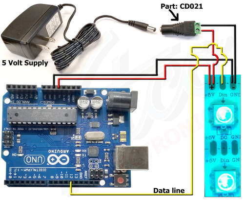
Connecting the Arduino is easy. From this point on, we will be talking about using the Arduino Uno R3 or R3 compatible.
You need to run 5 VOLTs from the power supply to the LED strip. Both POSITIVE and NEGATIVE need to be run to the LED strip.
Then you need to run a POSITIVE and NEGATIVE 5 VOLT from the power supply to the Arduino and connect the 5 VOLT positive to the “5V” header on the Arduino. And connect the 5 VOLT negative to the “GND” next to the “5V” header on the Arduino.
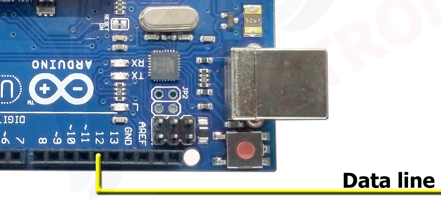
And last, you need to run a wire from the “Din” on the LED strip to the Arduino’s header pin that reads “12”. (Or you can use any data pin that you specify in your fastLED program. I just went with pin 12 for my project).
After these connections have been made, you can move on to:
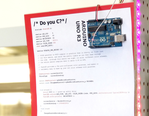
Programing the Arduino!
Here is where you are going to pull out the fastLED library.
Import the Library into the IDE. Do this by going to "Sketch">"Include Libarary">"Manage Libraries..."
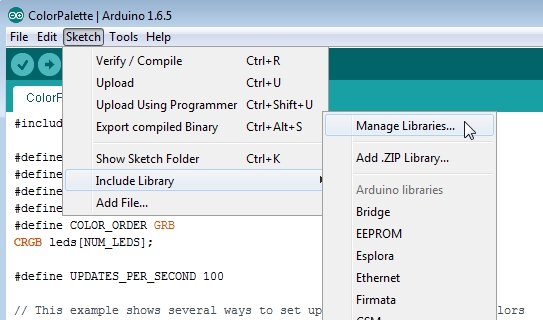
And search for "fastled" in the search box and hit the "ENTER" key.
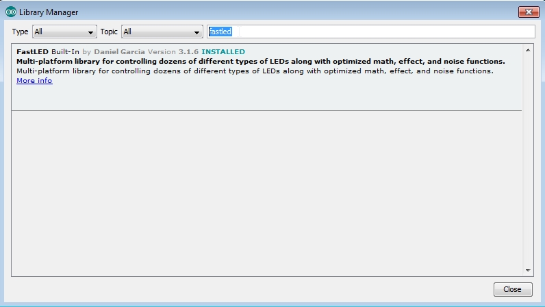
Select and install the "FastLED" library (which I have already done on my work PC). You may need to exit the Arduino IDE and
then, re-start start the Arduino IDE.
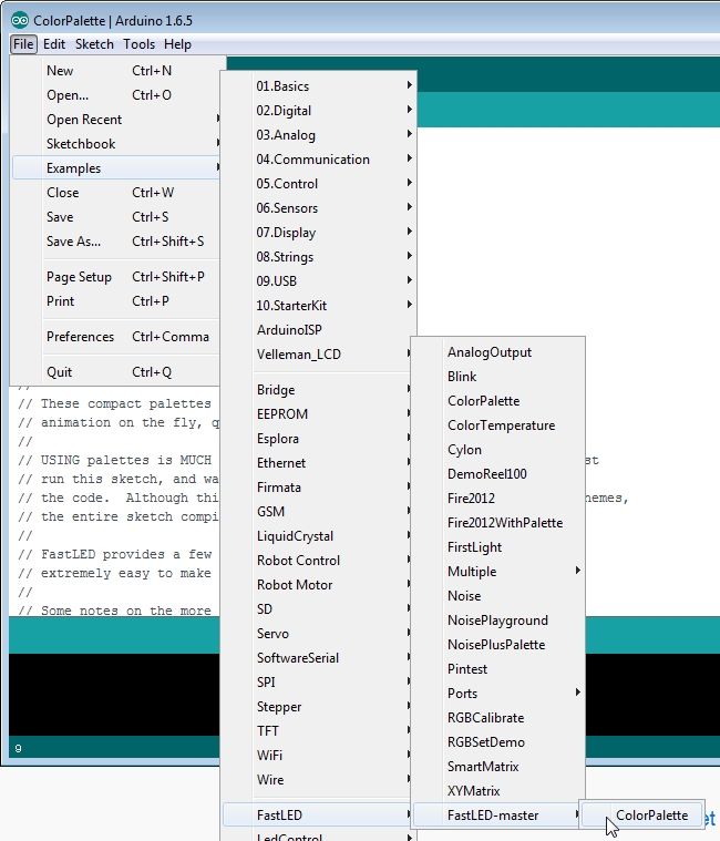
Now load up the sketch you want:
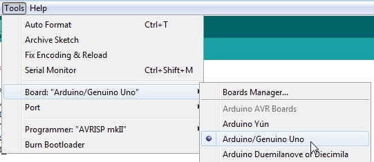
Then set the Arduino type in the IDE to "Arduino/Genuino Uno":
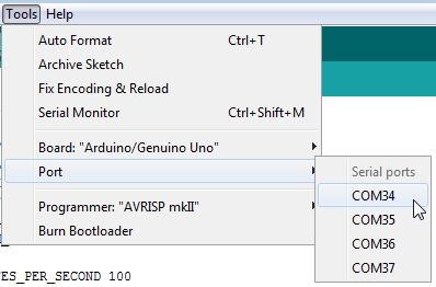
And don't forget to set your serial port to the correct one:
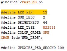
Next edit the "LED_PIN" to the one you are using for the strip on the Arduino board (we are using pin 12):
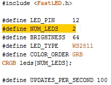
Now you want to define how many LEDs are in your RGB strip (mine only has two LEDs for this hookup demo):
I also like to change the brightness to "255" instead of the standard "64" that the sketch defaults to.
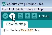
Then, last but not least, compile and upload the program to your Arduino:
After doing this, your LED strip should light up and show lots of bright colors and patterns. (assuming you've plugged in the ac adapter that is).
NOTES:
-Most people reccomend adding a 200 ohm resistor on the data line to protect the Arduino from possible surges. You would add this BETWEEN the Arduino and the LED strip. It can be anywhere on that line, but most people put it right next to the Arduino.
-The Arduino Uno does NOT have a voltage controller on the IO pins. If you use an unreliable power supply or supply any more than 5 volts DC on these header pins, you will fry your Arduino.
-Some people also like to add a filter capacitor on the the power line to filter dirty power or prevent power fluctuations that could freeze or reboot the Arduino. But the power supply I have in this tutorial has capacitors internally which do this.
 Cart (